Network
Various types of network traffic are required
in a virtualization environment. The nature and segregation of this
traffic should be fundamental to any good virtualization design. You
can aggregate and logically separate network traffic in many different
ways. Here, we delve into a few options and the reasoning behind each
to provide guidance. In addition, you have the option of adding vShield
technology as a layer on top of the virtual desktop environment to
further isolate View desktops from each other.
In Virtual Desktop Infrastructure, you can
actually have more storage I/O and network I/O requirements than server
virtualization environments. The reason is that the number of
read/write requests and amount of network data being transferred can be
greater than that of a virtual server environment. Therefore, in
addition to storage considerations, you also must carefully plan out
your network architecture.
Before we discuss the new capabilities that
have been added with vSphere 5, let’s go through a typical network
setup. In configuring your ESXi server, you have two connection types,
virtual machine and VMKernel connections, as shown in Figure 7.
Figure 7. Connection Type.
Virtual machine connections facilitate
traffic to and from the virtual machines on the ESXi host. VMkernel
handles traffic to and from the host hypervisor or ESXi host. VMkernel traffic
may include vMotion, storage (iSCSI and NFS), and connections to the
DCUI. All ports are connected to a logical switch or vSwitch. A vSwitch
is a piece of software that runs on the ESXi hosts that allows you to
aggregate virtual machines to map them to a physical network interface.
You can configure the number of ports and the maximum transfer units
(MTUs), as shown in Figure 8. MTUs are adjusted for support of, for example, jumbo frames in iSCSI networks.
Figure 8. vSwitch Properties.
The 1500 MTUs in Figure 8
refer to the size of the payload in bytes carried by the Ethernet frame
or Ethernet packet. Generally, a setting of 1500 bytes is appropriate
for most traffic except if your network infrastructure supports jumbo
frames. A jumbo frame increases the size of the payload. A jumbo frame
is a packet that carries a greater number of bytes, increasing the
payload of the packet. Because vSwitches are typically mapped to
physical network cards, you need dedicated vSwitches mapped to physical
network cards to be able to change the MTU to support jumbo frames. The
recommended MTU for jumbo frames is 9000 bytes or MTUs.
To properly configure support for jumbo
frames, you must ensure the max Ethernet frame size is consistent
across everything the packet will traverse. If it is not, the packet is
broken into fragments and sent piece by piece. This means to take
advantage of jumbo frames, every device along the path must have the
MTU adjusted.
The MTU must be
configurable on the storage device’s network card, the physical switch,
and either the NIC card within the ESXi host or the iSCSI software
initiator on the ESXi host. When you are planning to use iSCSI with
your VDI environment, it is best practice to isolate all traffic on a
separate VLAN segment. Often this segment is a flat layer two network,
which is restricted to just iSCSI initiators and targets.
It is possible to segregate traffic
physically or logically. Let’s look at a real-world example to better
illustrate this scenario. You have four types of traffic that you are
going to ensure have adequate throughput and are fully redundant. They
include the management console or DCUI, vMotion traffic, iSCSI storage
area traffic, and virtual desktop traffic. In this case, you need eight
physical network cards and four virtual switches. You can configure the
DCUI for active-passive for redundancy and the vMotion, storage, and
virtual desktop traffic to make use of both network cards. You need to
review whether the storage vendor supports jumbo frames because you may
need to customize the MTU or payload size on the VMkernel port to 9000
bytes and also the virtual switch. The benefit to this design is you
have dedicated physical paths or NICs to separate out the traffic. The
drawback to this design is you have a requirement for eight physical
network adapters. This configuration may be problematic if you were
looking to use small form factor, older blade servers. Newer blades
tend to use converged network adapters (CNAs) and software to enable
additional network paths and throughput. It is a standard to segment
traffic by vSwitch and physical NICs, as depicted in Figure 9.
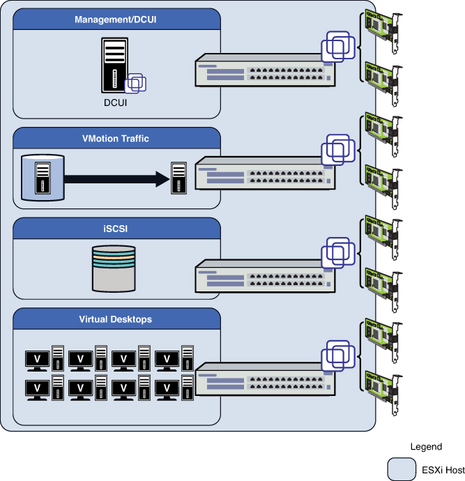
Figure 9. A typical vSwitch to physical NIC topology.
This method is not the
only one, however, because you can do it logically with port groups to
reduce the number of physical NICs required. Another way of achieving
the same design principle of segregating the network traffic is through
logical segregation of the traffic types using layer 2 technology or
VLAN tagging. ESXi fully supports the capability to tag packets to
enable the underlying network software to create different LAN segments
or virtual LAN (VLAN) segments across the same physical path. VLAN
tagging requires configuration on both the network hardware and the
ESXi servers.
Let’s look at how this configuration differs
logically. In this case, you aggregate all the physical NICs so that
they are connected to the same vSwitch. You then use VLAN IDs to create
four virtual LAN segments to segregate all the traffic. In addition,
you could add additional levels of redundancy by using port groups.
Port groups are similar to VLANs, but you can assign specific NICs to
the logical group and set active–active or active–passive network card
configurations. Although aggregation is less common on GB networks, it
is becoming increasingly prevalent on 10 GB networks. Be aware that 10
GB also further reduces the number of physical NICs required. Logically
separated, the configuration looks like the one shown in Figure 10.
Figure 10. Bonding and segregating by VLAN or port group.
The benefit to using both VLANs and port
groups is that you can use a smaller number of NICs but still have the
same logical segregation of network traffic. The only risk is that one
type of network traffic uses more bandwidth than it should, but you can
use traffic shaping and network I/O control to prioritize traffic so
that the virtual desktop traffic always receives priority, for example.
We go through a sample configuration after the installation of ESXi.
It is therefore more important to estimate
the network requirements properly and configure the number of physical
network cards to provide adequate throughput.
Storage
Although it is possible to build a virtual
environment based on local storage, doing so is highly inefficient
because many of the high availability features require shared storage.
Local storage also does not scale well because it becomes increasingly
difficult to move things around. This is not to say that you may not
make use of local storage for floating or nonpersistent desktops. We
discussed some interesting scenarios making use of local storage and
SSD drives in the introduction.
VMware supports Fiber Channel,
iSCSI, and NAS storage solutions. Although there used to be
recommendations based around performance for running one over the
other, this is less of a concern because the storage platforms have
evolved to drive better performance no matter what the underlying
storage technology is based on.