3. Skinning with OpenGL ES 1.1
All Apple devices at the time of this writing
support the GL_OES_matrix_palette extension under
OpenGL ES 1.1. As you’ll soon see, it works in a manner quite similar to
the OpenGL ES 2.0 method previously discussed. The tricky part is that
it imposes limits on the number of so-called vertex units and palette
matrices.
Each vertex unit
performs a single bone transformation. In the simple stick figure
example, we need only two vertex units for each joint, so this isn’t
much of a problem.
Palette matrices are
simply another term for bone matrices. We need 17 matrices for our stick
figure example, so a limitation might complicate matters.
Here’s how you can determine how many vertex
units and palette matrices are supported:
int numUnits;
glGetIntegerv(GL_MAX_VERTEX_UNITS_OES, &numUnits);

int maxMatrices;
glGetIntegerv(GL_MAX_PALETTE_MATRICES_OES, &maxMatrices);
Table 1 shows
the limits for current Apple devices at the time of this writing.
Table 1. Matrix palette limitations
| Apple device | Vertex units | Palette matrices |
|---|
| First-generation iPhone and iPod touch | 3 | 9 |
| iPhone 3G and 3GS | 4 | 11 |
| iPhone Simulator | 4 | 11 |
Uh oh, we need 17 matrices, but at most only
11 are supported! Fret not; we can simply split the rendering pass into
two draw calls. That’s not too shoddy! Moreover, since
glDrawElements allows us to pass in an offset, we can
still store the entire stick figure in only one VBO.
Let’s get down to the details. Since OpenGL
ES 1.1 doesn’t have uniform variables, it supplies an alternate way of
handing bone matrices over to the GPU. It works like this:
glEnable(GL_MATRIX_PALETTE_OES);
glMatrixMode(GL_MATRIX_PALETTE_OES);
for (int boneIndex = 0; boneIndex < boneCount; ++boneIndex) {
    glCurrentPaletteMatrixOES(boneIndex);
    glLoadMatrixf(modelviews[boneIndex].Pointer());
}
That was pretty straightforward! When you
enable GL_MATRIX_PALETTE_OES, you’re telling OpenGL
to ignore the standard model-view and instead use the model-views that
get specified while the matrix mode is set to
GL_MATRIX_PALETTE_OES.
We also need a way to give OpenGL the blend
weights and bone indices. That is simple enough:
glEnableClientState(GL_WEIGHT_ARRAY_OES);
glEnableClientState(GL_MATRIX_INDEX_ARRAY_OES);

glMatrixIndexPointerOES(2, GL_UNSIGNED_BYTE, stride,
                        _offsetof(Vertex, BoneIndices));
glWeightPointerOES(2, GL_FLOAT, stride, _offsetof(Vertex, BoneWeights));
We’re now ready to write some rendering code,
taking into account that the number of supported matrix palettes might
be less than the number of bones in our model. Check out Example 5 to see how we “cycle” the available
matrix slots; further explanation follows the listing.
Example 5. ES 1.1 Render method for vertex skinning
const SkinnedFigure& figure = m_skinnedFigure;

// Set up for skinned rendering:
glMatrixMode(GL_MATRIX_PALETTE_OES);
glEnableClientState(GL_WEIGHT_ARRAY_OES);
glEnableClientState(GL_MATRIX_INDEX_ARRAY_OES);

glBindBuffer(GL_ELEMENT_ARRAY_BUFFER, figure.IndexBuffer);
glBindBuffer(GL_ARRAY_BUFFER, figure.VertexBuffer);

glMatrixIndexPointerOES(2, GL_UNSIGNED_BYTE, stride,
                        _offsetof(Vertex, BoneIndices));
glWeightPointerOES(2, GL_FLOAT, stride, _offsetof(Vertex, BoneWeights));
glVertexPointer(3, GL_FLOAT, stride, _offsetof(Vertex, Position));
glTexCoordPointer(2, GL_FLOAT, stride, _offsetof(Vertex, TexCoord));


// Make several rendering passes if need be,
// depending on the maximum bone count:
int startBoneIndex = 0;
while (startBoneIndex < BoneCount - 1) {

    int endBoneIndex = min(BoneCount, startBoneIndex + m_maxBoneCount);

    for (int boneIndex = startBoneIndex;
         boneIndex < endBoneIndex;
         ++boneIndex)
    {

        int slotIndex;

        // All passes beyond the first pass are offset by one.
        if (startBoneIndex > 0)
            slotIndex = (boneIndex + 1) % m_maxBoneCount;
        else
            slotIndex = boneIndex % m_maxBoneCount;

        glCurrentPaletteMatrixOES(slotIndex);
        mat4 modelview = figure.Matrices[boneIndex];
        glLoadMatrixf(modelview.Pointer());
    }

    size_t indicesPerBone = 12 + 6 * (NumDivisions + 1);
    int startIndex = startBoneIndex * indicesPerBone;
    int boneCount = endBoneIndex - startBoneIndex;

    const GLvoid* byteOffset = (const GLvoid*) (startIndex * 2);
    int indexCount = boneCount * indicesPerBone;
    glDrawElements(GL_TRIANGLES, indexCount,
                   GL_UNSIGNED_SHORT, byteOffset);

    startBoneIndex = endBoneIndex - 1;
}
|
Under our system, if the model has 17 bones
and the hardware supports 11 bones, vertices affected by the 12th matrix
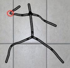
should have an index of 1 rather than 11; see Figure 3 for a depiction of how this works.

Unfortunately, our system breaks down if at
least one vertex needs to be affected by two bones that “span” the two
passes, but this rarely occurs in practice.
4. Generating Weights and Indices
The limitation on available matrix palettes
also needs to be taken into account when annotating the vertices with
their respective matrix indices. Example 6
shows how our system generates the blend weights and indices for a
single limb.
Example 6. Generation of bone weights and indices
for (int j = 0; j < NumSlices; ++j) {

    GLushort index0 = floor(blendWeight);
    GLushort index1 = ceil(blendWeight);
    index1 = index1 < BoneCount ? index1 : index0;

    int i0 = index0 % maxBoneCount;
    int i1 = index1 % maxBoneCount;

    // All passes beyond the first pass are offset by one.
    if (index0 >= maxBoneCount || index1 >= maxBoneCount) {
        i0++;
        i1++;
    }

    destVertex->BoneIndices = i1 | (i0 << 8);
    destVertex->BoneWeights.x = blendWeight - index0;
    destVertex->BoneWeights.y = 1.0f - destVertex->BoneWeights.x;
    destVertex++;

    destVertex->BoneIndices = i1 | (i0 << 8);
    destVertex->BoneWeights.x = blendWeight - index0;
    destVertex->BoneWeights.y = 1.0f - destVertex->BoneWeights.x;
    destVertex++;

    blendWeight += (j < NumSlices / 2) ? delta0 : delta1;
}
|
In Example 6, the
delta0 and delta1 variables are
the increments used for each half of limb; refer to Table 2 and flip back to Figure 2 to see how this works.
Table 2. Bone weight increments
| Limb | Increment |
|---|
| First half of upper arm | 0 |
| Second half of upper arm | 0.166 |
| First half of forearm | 0.166 |
| Second half of forearm | 0 |
For simplicity, we’re using a linear falloff
of bone weights here, but I encourage you to try other variations. Bone
weight distribution is a bit of a black art.
5. Watch Out for Pinching
Before you get too excited, I should warn you
that vertex skinning isn’t a magic elixir. An issue called
pinching has caused many a late night for animators
and developers. Pinching is a side effect of interpolation that causes
severely angled joints to become distorted (Figure 3).

If you’re using OpenGL ES 2.0 and pinching is
causing headaches, you should research a technique called dual
quaternion skinning, developed by Ladislav Kavan and
others.