Although CorelDRAW is a drawing program and not a
modeling application such as Autodesk 3D Studio, you can indeed get
dimensional effects with the Extrude tool to make a simple drawing such
as this logo pop off the page... or off a T-shirt.
Using the Interactive Extrude Tool
The Interactive Extrude tool is a basic tool for
defining edges that appear to extend into the third dimension of space,
adding depth to the height and width of the object to which you apply
this tool. However, once you’ve added depth to a selected object, it
might not be apparent to you or your audience that this is a 3D shape
because of the way it’s “posed” on the drawing page. By default, the
Interactive Extrude tool creates edges that appear mostly behind the
extruded shape, because of an optical principle known as a vanishing
point. A vanishing point
(tell your friends you know that da Vinci discovered vanishing points)
is the point in 3D space where, if you drew lines marking the angles of
an object with depth, the lines would converge. You see vanishing points
all the time: say you’re standing on train tracks (when a train isn’t
coming), and you look straight down the tracks. Where the rails converge
is the vanishing point.
Similarly, to get the most out of the Extrude feature
in CorelDRAW, you want to view an extruded shape off-axis, not
straight-on, because looking at objects directly face-front removes the perspective
from the object, flattening its appearance. CorelDRAW has additional
features after you’ve made a shape into an extruded shape, one of which
is a rotation feature—yes, you can
rotate a 3D object on your drawing page—to show off all three possible
facing sides of the extruded shape. An object viewed in ¾ view shows off
the most visual detail (this is why portrait photographers try to get
customers to point their head off-camera), and the following tutorial
takes you through object extruding, rotating, and how to interactively
adjust the depth of the object you extrude.
Tip
Extruded sides of an object
by default inherit the fill from the parent object. Therefore, because
the gear in this example has a fountain fill, so do the objects that
make up the sides of the gear. Fountain fills aren’t as visible when
they’re on the 3D face of a shape that has lighting, which you’ll add in
this tutorial. However, you can modify the fill of the control object
(the shape you started with), the extrude: CTRL-click to select it from the group of shapes that dynamically make up the extruded object, and then modify the fill.
Making a Logo into a 3D Logo
With
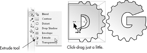
the D gear selected on the drawing page, click-hold the Effects group
button (just above the familiar-shaped Eyedropper tool) on the toolbox
to reveal the flyout that has the Extrude tool. Select the Extrude tool
from the flyout.
Click-drag just a little, straight down on the object, as shown in Figure 1. Just a little does the trick—you’re establishing an extruded object and setting a vanishing point for the object at the same time. Stop dragging when one of the sides of the extrude object is visible. Resist
the temptation that accompanies the natural thought, “the more I
click-drag, the more extruded the gear will be.” Nope—the more you drag,
the farther the vanishing point is defined relative to the object, and
it’s very easy to set the vanishing point clear off the page, and
possibly extend it to the Theophilus crater on the moon.
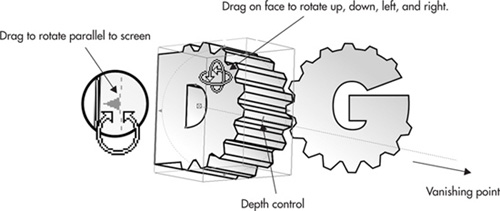
Double-click the extrude group of
objects while the vanishing point and other onscreen indicators are
visible. You’re now in a mode where you can rotate the extrude objects
onscreen in three dimensions. If you deselected the shape, double-click
an extrude area, and then single-click (this can be done with the
Extrude or the Pick tool). Point the D gear a little upwards by
click-dragging up and just a little to the left on the face of the
object, as Figure 2
shows. The goal here is to create a visually dynamic logo that the
audience is intimidated by, so the audience is looking up at this
goliath of a company (yeah, yeah, it’s trite, but it works). If
necessary, drag one of the markers along the green ring encircling the D
gear to rotate the object parallel to the screen; think of the ticks on
a clock face, and you’re rotating the D gear from 9 to 8 o’clock, for
example.
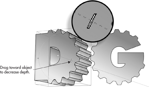
Click-drag
the marker shown in the following illustration toward the gear to
decrease its depth. Dragging it away from the gear makes it deeper, and
although this is illuminating advice, you will probably never need to
make an extruded shape fatter. Also note that the vanishing-point line,
the light blue dotted line, extends way off the page. This is of
absolutely no consequence in your design work. The vanishing point does
not print, and if your gear illustration looks fine right now, it is
fine, regardless of onscreen guides.
Tip
At
any time in the future, you can change the rotation of the extruded
shape, as well as the depth—it’s a dynamically editable object. To
quickly display the property bar options and the depth control marker on
the object, and switch to the Interactive Extrude tool, you can
double-click the object with the Pick tool.
Adding Lighting and a Bevel
Let’s polish the D gear part of the logo now; the G
gear can take on the same look as the D once it’s completed by copying
its properties to the G. The Extrusion Lighting feature is available
only when an object is extruded and is located on the property bar—it’s
the light bulb button. Lighting can be performed using one or up to
three individual lights, and each light can occupy one of 16 possible
positions around the object.
As an embellishment, you’ll add a very small bevel
edge to the front face of the D gear, just to add a little highlight to
the edge where the extrude and the object meet. Realistically,
industrial gears don’t often have beveled edges, but they also aren’t
shaped in alphanumeric characters! This is Art and not a blueprint.
Here’s how to add lighting and the bevel edge to the D gear.