1. | Start a new Basic Flowchart drawing.
|
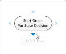
2. | Drag a Start/End shape onto the drawing page. You can enter some text, such as Start.
|
3. | Notice
that when your mouse cursor hovers over the shape, four blue
AutoConnect arrows appear around the edges. If you move your mouse
cursor over one of these arrows, you see the mini-toolbar, as shown in Figure 2. This feature enables you to insert one of the top four Quick Shapes from the currently visible stencil.
|
4. | Click
on one of the shapes in the mini-toolbar. Notice that the shape is
added to your diagram, aligned with the previous shape, and
automatically connected.
|
5. | Move
your new shape around. Notice that the connector stays glued to both
shapes. Notice also that the connector wanders around the edges of the
shapes so that the nearest sides are connected.
|
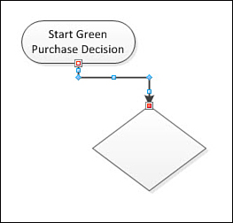
6. | Select
the connector. Notice that it has two endpoint handles instead of the
eight blue resizing handles that the Start/End shape and other 2D shapes
have. The endpoint handles are red, indicating that the connector is
glued at both ends to the other flowchart shapes. The connector also has
some smaller blue handles that allow you to reposition bends and
corners.
|
7. | Drag
a Custom 2 shape onto the page, away from the other two shapes. It is
below the Quick Shapes line in the Basic Flowchart Shapes stencil, so
you might have to scroll the stencil window to see it. Since it isn’t
connected to any shapes, let’s connect it to the flow using a more
manual method in the next few steps.
|
8. | On the Home tab, select the Connector tool from the Tools group.
|
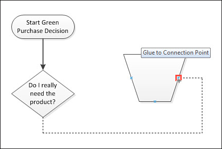
9. | Connect
the Custom 2 shape to the process by clicking on one shape, dragging
over another, and then releasing the mouse button. Notice the red
highlights when the mouse cursor is positioned over a shape.
A red box around the entire shape means glue dynamically:
the connector wanders around the shape to find the nearest side.
Mousing near the edges of the shape reveals small red squares with blue
Xs inside, shown in Figure 4. Connecting to these makes point-to-point glue, where the connector stays attached to this point, no matter where you position the flowchart shapes.
|
10. | Switch back to the Pointer tool, located just above the Connector tool (or just press Ctrl+1).
|
11. | Select and delete the Custom 2 shape that you added in step 7. Notice that the connector is automatically deleted along with it!
|
12. | Drag
another shape from the stencil and drop it on the connector between the
two remaining shapes. Don’t drop the shape until you see red highlights
on both ends of the connector.
This highlighting tells you that Visio will automatically help you with
the insertion of the step. When you let go, Visio splits the connector
in two and glues the new shape to the pieces. It also dynamically slides
the existing shapes out of the way to make room for the newcomer.
|
13. | Delete
the shape you just added in the preceding step. Notice that the two
connectors heal to become just one. However, they do not automatically
slide closer together to close the gap.
|
14. | Drop another shape onto the page, unconnected to the others.
|
15. | To
connect it to another shape, pause the mouse cursor over the shape
until the AutoConnect arrows appear. Now click and drag from one of the
arrows. You can actually drag a connector out of the arrow and connect
it to another shape.
|
16. | Experiment
with gluing the dangling end to a target shape using dynamic or point
to point glue. Once the connector is glued, you can still select it and
then grab a handle and move it to another shape or another connection
point on the same shape. Try re-connecting ends of the connector to
other shapes and connection points on other shapes. |