1. Stacking order
Within a single layer,
Flash stacks items of the same type in the same order they are placed or
created, with the most recent item on top, subject to the kind of item. The rules that control the stacking order of various kinds of items are simple:
Within a layer, ungrouped raw shapes or lines are always at the bottom
level, with the most recently drawn shape or line at the top of that
layer's stack. Furthermore, unless you take precautions, drawn items
either compound with, or cut into, the drawing beneath them.
Groups, drawing objects, and symbols (including bitmaps) stack above lines and shapes in the overlay
level. To change the stacking order of several items, it's often
advisable to group them first.
To change the stacking order within a layer, first select the item that you want to move. Then, do one of the following:
To move the item to the top of the stacking order, choose Modify => Arrange => Bring to Front (Alt+Shift+↑/Option+Shift+↑).
To move an item to the bottom of the stacking order, choose Modify => Arrange => Send to Back (Alt+Shift+↓/Option+Shift+↓).
To move the item up one position in the stacking order, choose Modify => Arrange => Bring Forward (Ctrl+↑/ +↑).
+↑).
To move the item down one position in the stacking order, choose Modify => Arrange => Send Backward (Ctrl+↓/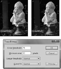 +↓).
+↓).
Remember the stacking-order
rules: You won't be able to bring an ungrouped drawing above a group or
symbol. If you need that drawing on top, group it and then move it, or
place it on a separate layer.
To stack an item in a lower
layer above an item in a higher layer, you simply change the order of
the layer among the other layers: First, activate the layer, and then
drag the Layer bar to the desired position in the layer stack of the
timeline.
|
Regardless of the number of
layers in a Flash project (.fla), neither the file size nor the
performance of the final .swf file is adversely affected because Flash
flattens layers upon export.
|
|
2. Grouping
Grouping shapes or lines makes them easier to handle. Instead of
manipulating a single item, group several items to work with them as a
single unit. Grouping also prevents shapes from being merged with or
cropped by other shapes. In addition, it's easier to control the
stacking order of groups than it is to control ungrouped drawings.
Here's how to create groups:
Use Shift+click to select multiple items or drag a selection box around everything that you want to group. This can include any combination of items: shapes, lines, and symbols — even other groups.
Choose Modify => Group (Ctrl+G/ +G). The selected elements are now grouped.
To ungroup everything, select the group and then use Modify => Ungroup (Ctrl+Shift+G/ +Shift+G).
Ungrouping only separates grouped items; it does not break apart
bitmaps, symbol instances, or text as the Break apart command does.
|
Be careful when ungrouping. Your newly ungrouped drawings may alter or eliminate drawings below in the same layer.
|
|
To edit a group:
Select the group and then choose Edit => Edit Selected, or double-click the group. Everything on the Stage — except for items in the group — is dimmed, indicating that only the group is editable.
Make changes in the same way you would edit individual primitive shapes or symbols.
If there are other groups or symbols included in a larger group, you'll
have to click in deeper to edit those items. You can keep
double-clicking on compound groups to gradually move inside to the
deepest level or primitive shape available for editing. You can use the
location labels to move back out level by level (or double-click an
empty area of the Stage), or go to Step 3 to return to the Main
Timeline.
To stop editing the group, choose Edit => Edit All, or use the location labels to return to the main scene. Other items on Stage return to normal color.
3. Applying Break apart
The Modify => Break apart command (Ctrl+B/+B)
is rather like an Undo command for groups, drawing objects, and symbols
as well as a deconstruction tool for text and bitmaps. To use Break
apart, simply select an item and then apply the command. Occasionally
you must apply the Break apart command more than once to reduce a
compound group to its core shapes. When applied to a symbol instance,
Break apart reduces the instance to raw shapes that no longer are linked
to the original symbol stored in the library.
3.1. Breaking apart text
Text reduced to shapes by
using Break apart can be filled with gradients and bitmaps and also
modified with the shape Transform options. Figure 1
illustrates how text is broken apart in two stages so that the original
block (left) is first separated into individual letters (center), and
then when broken apart a second time, it is reduced to shapes (right).

|
Breaking apart complex symbols or large text blocks can add to the file size of your final movie.
|
|
|
To demonstrate how text
characters can be modified after they've been converted to shapes, I
have applied some gradient fills to create the illusion of shiny metal
letters. The file for this effect is titled metalType.fla and is included in the ch09 folder of the CD-ROM. Start with a document that has a dark gray background.
First
type a word or words on the Stage to create a text block. This effect
works best if applied to a bold, sans serif font at a fairly large point
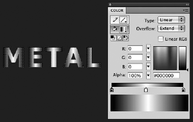
size. I used Verdana bold set at 50 pt. Select the text block and apply the Break apart command (Ctrl+B/+B) once to break the text block into individual letters, and then a second time to convert the letters into shapes. With
the letter shapes still selected, load a default grayscale linear
gradient into the Color panel and then adjust it so the gradient is dark
at each end with a highlight in the center. Set the left and far right
Color pointers to black (#000000) and then add a new Color pointer in the center of the Edit bar and set it to white (#FFFFFF), as shown in Figure 2.
Use
the Gradient Transform tool to rotate the gradient fill clockwise to a
45-degree angle in each letter shape. You may also scale each fill
slightly or adjust individual center points to align the highlight on
each letter, as shown in Figure 3.

To
create a more three-dimensional look, make a copy of all the letter
shapes in a new layer below the current layer. Use the Copy (Ctrl+C/+C) and Paste (Ctrl+V/+V)
commands. Turn the visibility of the original layer off (click the Eye
icon) for now so you can see only the copied letter shapes. Select
all the copied letter shapes, and using the Color panel, reverse the
gradient fill colors. Set the center Color pointer to black and both end
Color pointers to white, as shown in Figure 4.

Use the Modify => Shape => Expand Fill command to expand the fill in all the selected letters by 2 pixels. If
you turn the visibility of both layers back on, you should see that you
now have two opposing gradient fills, and the copied letter shapes are
slightly larger than the original letter shapes. Figure 5 compares the letters with the original gradient and the letters with the modified gradient.

Lock
the original layer, and then select all the copied letter shapes on the
lower layer and drag them behind the original letter shapes so that
they're aligned just slightly above and to the right of the original
shapes. This creates the illusion of a metallic beveled edge on the
original letter shapes, as shown in Figure 6.

|
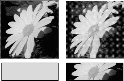
3.2. Breaking apart bitmaps
When applied to bitmaps
placed in the Document window, Break apart enables you to select the
bitmap image with the Eyedropper tool to apply as a fill to other
shapes. This is not the same as tracing a bitmap, which reduces the vast
number of colors in a bitmap to areas of solid color and converts it to
vector format, as described in the section that follows. Figure 7
shows an imported bitmap placed on the Stage and sampled with the
Eyedropper tool to create a colored fill in the rectangle below (left)
compared to the same bitmap broken apart and sampled with the Eyedropper
tool to create an image fill in the rectangle below (right).
It isn't necessary to break apart bitmaps to use as fills because they can be specified with the Mixer panel.
But breaking apart bitmaps enables you to selectively edit them and
modify the visible area of the bitmap with the shape Transform options.
|
Although you can apply the
Distort and Envelope modifiers of the Free Transform tool to a bitmap
after it has been broken apart, they may not give you the result you
expect. Instead of distorting or warping the actual bitmap image, you'll
find that these modifiers reveal how Flash "sees" bitmap fills. The
visible area of the bitmap is not really treated as a shape but rather
as a mask, or shaped window, that enables a certain part of the bitmap
to be visible. You can distort or warp the viewable area, but the bitmap
itself is not modified, as it is when you apply the Rotate or Skew
modifiers.
|
|
Figure 8
illustrates a bitmap that has been broken apart (left) so that colored
areas in the background of the image can be selected with the Magic Wand
option of the Lasso tool (center) and then deleted to leave the flower
floating on the white Stage (right). You can clean up any stray areas of
unwanted color by using the Lasso tool or the Eraser tool.
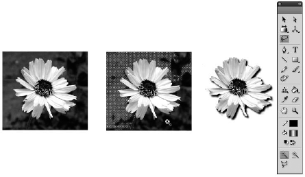
4. About the Magic Wand option
You use the Magic Wand option of the Lasso tool (shown at the bottom of the Tools panel in Figure 9.40)
to select ranges of a similar color in either a bitmap fill or a bitmap
that's been broken apart. After you select areas of the bitmap, you can
change their fill color or delete them, without affecting the Bitmap
Swatch in the Color panel. You can adjust what pixels the Magic Wand
picks up by modifying the Threshold and Smoothing settings in the dialog
box opened by clicking the Magic Wand settings button in the Options
area of the Tools panel.
4.1. Magic Wand Threshold setting
The Threshold setting
defines the breadth of adjacent color values that the Magic Wand
includes in a selection. Values for the Threshold setting range from 0
to 200 — the higher the setting, the broader the selection of adjacent
colors. Conversely, a smaller number results in the Magic Wand making a
narrower selection of adjacent colors.
A value of zero results in a
selection of contiguous pixels that are all the same color as the
target pixel. With a value of 20, clicking a red target pixel with a
value of 55 selects all contiguous pixels in a range of values extending
from red 35 to red 75. (If you're comparing selection behavior with
Photoshop, you'll notice a slight difference because in Photoshop a
Tolerance setting of 20 selects all contiguous pixels in a tighter range
of values extending from red 45 to red 65.)
4.2. Magic Wand Smoothing setting
The Smoothing setting
of the Magic Wand option determines to what degree the edge of the
selection should be smoothed. This is similar to anti-aliasing.
(Anti-aliasing dithers the edges of shapes and lines so that they look
smoother on-screen.) The options are Pixels, Rough, Normal, and Smooth.
Assuming that the Threshold setting remains constant, the Smoothing
settings differ as follows:
Pixels: Clings to the rectangular edges of each pixel bordering similar colors.
Rough: With this setting, the edges of the selection are even more angular than with Pixels.
Normal: Results in a selection that's somewhere between Rough and Smooth.
Smooth: Delivers a selection with more rounded edges.
5. Tracing bitmaps
You use the Trace bitmap
command to convert an imported image from a bitmap to a native Flash
vector graphic with discrete, editable areas of color. This unlinks the
image from the original symbol in the library (and also from the Bitmap
Swatch in the Color panel). You can create interesting bitmap-based art
with this command. However, if your intention is to preserve the look of
the original bitmap with maximum fidelity, you must work with the
settings — and you will most likely find that the original bitmap is
actually smaller in file size than the traced vector image. Figure 9
includes a selected bitmap image on the left and the final vector image
that resulted from the settings shown in the Trace Bitmap dialog box on
the right.
|
The Trace Bitmap dialog box
includes a handy Preview button that enables you to test settings before
you apply them. The preview is rendered more quickly than the final
trace conversion, and using this option saves you from having to use the
Undo command and then reopen the Trace Bitmap dialog box each time you
want to try a different setting.
|
|
To trace a bitmap, follow these steps:
Use the Selection tool to select the bitmap that you want to trace. It can be in Edit mode or directly on the Stage.
Choose Modify => Bitmap => Trace Bitmap to open the Trace Bitmap dialog box and set the options according to your needs:
Color threshold:
This option controls the number of colors in your traced bitmap. It
limits the number of colors by averaging the colors based on the
criteria chosen in Color threshold and Minimum area. Color threshold
compares RGB color values of adjacent pixels to the value entered. If
the difference is lower than the value entered, adjacent pixels are
considered the same color. By making this computation for each pixel
within the bitmap, Flash averages the colors. A lower Color threshold
delivers more colors in the final vector graphic derived from the traced
bitmap. The range is between 0 and 500, with a default setting of 100.
Minimum area:
This value is the radius, measured in pixels, which Color threshold
uses to describe adjacent pixels when comparing pixels to determine what
color to assign to the center pixel. The range is between 1 and 1,000,
with the default setting being 8.
Curve fit:
This value determines how smoothly outlines are drawn. Select Very
Tight if the shapes in the bitmap are complex and angular. If the curves
are smooth, select Very Smooth.
Corner threshold: This setting determines how sharp edges are handled; choose Many Corners to retain edges and Few Corners to smooth the edges.
Click OK.
Flash traces the bitmap, and the original pixel information is
converted to vector shapes. If the bitmap is complex, this may take a
while. Depending on the settings you have chosen, the final look of the
traced graphic can vary between being very close to the original or very
abstracted.
|
If your objective is for your
traced bitmap to closely resemble the original bitmap, set a low Color
threshold and a low Minimum area. You'll also want to set the Curve fit
to Pixels and the Corner threshold to Many Corners. Be aware that using
these settings may drastically slow the tracing process for complex
bitmaps and result in larger file sizes. If animated, such bitmaps may
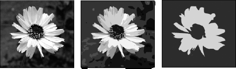
also retard the frame rate dramatically.
|
|
As shown in Figure 10,
the traced bitmap can vary in how closely it resembles the original
bitmap. The image in the center was traced with lower settings to
achieve a more detailed image: Color threshold of 25, Minimum area of 2
pixels, Curve fit of Pixels, and Corner threshold of Many Corners. The
image on the right was traced with higher settings to create a more
abstract graphic image: Color threshold of 300, Minimum area of 25
pixels, Curve fit of Very Smooth, and Corner threshold of Few Corners.
|
If you drag a bitmap from the
Library panel onto the Stage and then attempt to acquire the bitmap fill
by first tracing the bitmap and then clicking with the Eyedropper tool,
be careful of how selection affects the results. If the traced bitmap
is still selected, clicking with the Eyedropper tool acquires the
nearest color and replaces the entire traced bitmap with a solid fill of
the acquired color. If the traced bitmap is not selected, the
Eyedropper tool simply acquires the nearest solid color and loads it
into the fill color chip. |